UPF (Unified Power Format) Construct Example for ASIC Low-Power Design
UPF is used to define power domains, power states, isolation, retention, and level shifting in a design. Below is a practical example with explanations for each key construct.

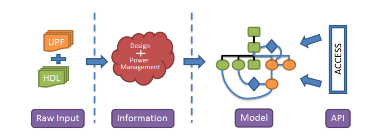
UPF Information Model
1. Basic UPF Example: Power Domain Definition
# Load UPF library
load_upf stdcell.upf

# Define power domains
create_power_domain PD_TOP \
  -include_scope \
  -elements {.}  # Top-level domain

create_power_domain PD_CPU \
  -elements {u_cpu*} \  # All CPU hierarchy
  -supply {primary_rail}  # Main power supply

create_power_domain PD_MEM \
  -elements {u_ram*} \  # All memory instances
  -supply {mem_vdd}     # Separate memory supply
2. Power Supply Network
# Define power nets and switches
create_supply_net VDD -domain PD_TOP
create_supply_net VSS -domain PD_TOP  # Ground

create_supply_net MEM_VDD -domain PD_MEM
create_supply_port VDD_PAD -domain PD_TOP

# Connect supplies
connect_supply_net VDD -ports VDD_PAD
connect_supply_net MEM_VDD -domain PD_MEM -supply {VDD}  # Derived from VDD
3. Power States & Transitions
# Define power states
add_power_state PD_CPU \
  -state {ON} \
  -supply {primary_rail -voltage 0.9}  # Nominal voltage

add_power_state PD_CPU \
  -state {OFF} \
  -supply {primary_rail -voltage 0.0}  # Power-gated

add_power_state PD_MEM \
  -state {RETENTION} \
  -supply {mem_vdd -voltage 0.3}  # Low-power retention mode
4. Isolation & Retention Strategies
(A) Isolation Cells (Prevent Unknowns During Power-Down)
set_isolation iso_cpu \
  -domain PD_CPU \
  -isolation_power_net VDD \
  -isolation_ground_net VSS \
  -clamp_value 0 \  # Tie outputs to 0 when OFF
  -applies_to outputs

set_isolation_control iso_cpu \
  -domain PD_CPU \
  -isolation_signal power_enable \  # Control signal
  -location parent  # Isolation cell placement
(B) Retention Registers (Save State During Power-Down)
set_retention ret_cpu \
  -domain PD_CPU \
  -retention_power_net VDD \
  -retention_ground_net VSS \
  -save_signal save_enable \  # Save state signal
  -restore_signal restore_enable  # Restore signal
5. Level Shifters (Voltage Crossing)
set_level_shifter ls_mem \
  -domain PD_MEM \
  -applies_to inputs \  # Signals entering PD_MEM
  -location self \      # Place LS inside PD_MEM
  -rule low_to_high \   # 0.9V → 1.2V
  -threshold 0.6        # Voltage threshold
6. Power Switches (For Power Gating)
create_power_switch psw_cpu \
  -domain PD_CPU \
  -input_supply_port {in VDD} \
  -output_supply_port {out primary_rail} \
  -control_port {ctrl power_enable} \
  -on_state {ON ctrl {1}} \
  -off_state {OFF ctrl {0}}
7. UPF Constraints for Synthesis/P&R
# Synopsys DC/ICC2 commands to apply UPF
load_upf design.upf
commit_upf  # Validate and apply UPF
Key UPF Constructs Summary
| Construct | Purpose | Example |
|---|---|---|
create_power_domain | Define voltage regions. | -elements {u_cpu*} |
create_supply_net | Declare power nets. | -domain PD_TOP |
set_isolation | Prevent X-propagation. | -clamp_value 0 |
set_retention | Save register state during power-off. | -save_signal save_enable |
set_level_shifter | Handle voltage crossings. | -rule low_to_high |
create_power_switch | Control power gating. | -on_state {ON ctrl {1}} |
Debugging UPF Issues
- Check Power Domain Mapping
report_power_domain -verbose- Verify Isolation/Rentention
   report_isolation -all
report_retention -all- Validate Supply Connections
report_supply_networkConclusion
- UPF ensures consistent low-power implementation across RTL-to-GDSII.
- Key steps: Power domains → Supplies → Isolation → Retention → Level shifters.
- Tool support: Synopsys (DC, ICC2), Cadence (Genus, Innovus), Siemens (Catapult).

Power switch control tied off