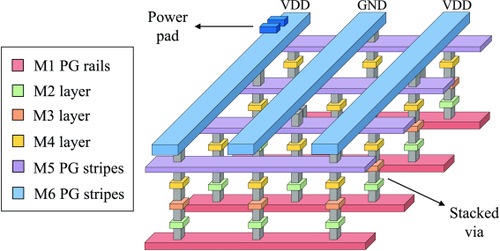
During Physical Design power grid planning, how do we calculate the WIDTH of the power stripes in order to meet the required IR drop limit?
Calculating the width of power straps during ASIC physical design involves ensuring that the IR drop along the power delivery network (PDN) stays within the acceptable limits defined by the design specifications. Here’s a step-by-step approach:
1. Understand the Power Strap Design Requirements
-
IR Drop Budget (Vdrop):
-
The allowable voltage drop from the power supply (e.g., VDD) to the furthest point of the PDN.
-
-
Maximum Current (Imax):
-
The total current drawn by the block or design in the worst-case scenario.
-
-
Resistivity (ρ):
-
Material resistivity (e.g., copper or aluminum).
-
-
Current Density Limit (Jmax):
-
The maximum current density allowed for the metal layer to avoid electromigration issues.
-
2. Formulate the Power Strap Width Calculation
The IR drop is a function of resistance (R) and the current (I) flowing through the strap:
Vdrop=I*R
Resistance of the Power Strap:
The resistance of a metal strap is given by:
R=ρ ( L) / (W * t)
Where:
-
ρ: Resistivity of the metal (Ohm·cm).
-
L: Length of the strap (cm).
-
W: Width of the strap (cm).
-
t: Thickness of the strap (cm).
Required Strap Width (W):
Rearranging to find the strap width:
W=ρ⋅I⋅L / (t⋅Vdrop)
3. Consider Parallel Power Straps
If multiple straps are used, the effective resistance decreases as they are in parallel. The equivalent width becomes:
Wtotal=ρ*I*L / (t*Vdrop*N)
Where N is the number of parallel straps.
4. Ensure Compliance with Current Density Limits
Check that the strap width also satisfies the current density constraint:
W≥It⋅Jmax
This ensures the strap can carry the required current without violating electromigration rules.
5. Additional Factors to Consider
-
Layer Resistance:
-
Resistance varies by metal layer (e.g., M1, M2, etc.).
-
Higher metal layers generally have lower resistivity and larger thickness.
-
-
Grid Density:
-
More straps or a denser power grid can reduce the width requirement per strap.
-
-
Via Resistance:
-
Account for resistance due to vias connecting straps across layers.
-
-
Dynamic and Static Current:
-
Dynamic IR drop is caused by switching currents, while static IR drop is caused by leakage. Consider both in the calculation.
-
Example Calculation
Given:
-
I=10 A (current)
-
ρ=2.2×10⁻⁶ Ω \cdotpcm (copper resistivity)
-
L=1 cm (strap length)
-
t=0.35 μm (metal thickness)
-
Vdrop=50 mV
-
Jmax=1×10⁶ A/cm2
Strap Width:
-
Calculate based on IR drop:
W=ρ⋅I⋅Lt⋅Vdrop
Substituting values:
W=(2.2×10−6)⋅10⋅1(0.35×10−4)⋅0.05≈1.26 cm
-
Validate against current density:
W≥It⋅Jmax
Substituting:
W≥10(0.35×10−4)⋅(1×106)≈2.86 cm
The current density constraint dominates, so W=2.86 cm.
Powered By EmbedPress


