Estimating the switch cells or Power mixes during floorpan can be challenging if not done properly.
Over estimation of the switch cell count for conservative IR drop can lead to over-design and higher utilization and negatively impact routing and congestion.
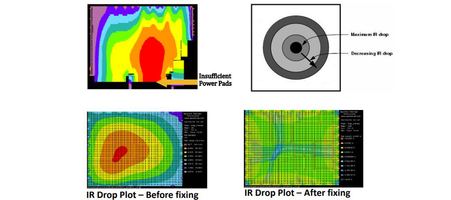
Under estimation of the switch cell count for IR drop can help to lower utilization, however, it will cause significant IR drop to the region and be challenging to close IR drop within signoff limits.
Here are typical scenarios and good guidelines to to help with Power Mux /Switch count calculations
First calculate the peak current demands for both the CX and MX portions for the given region.
Assuming 4 memories switching in the MX/ LPI_MX domain
Max simultaneous switching: 2 LB in WRITE operation + 2 LB in READ operation
Peak current demand is 60mA (WRITE mode) + 30mA (READ mode) for MX = 2*60 + 2*30 = 180mA
Then calculate the Max. Resistance using the peak current demand and allowable IR Drop over that region.
- Allow static IR drop: 10mV (V=IR) —> 10mV = 180mA * R —> R= 10/180 —> No. of APM = 1/R = 18
- Allow static IR Drop: 15mV (V=IR) —> 15mV = 180mA * R —> R=15/180 —> No. of APM = 1/R = 12
- Allow static IR Drop: 20mV (V=IR) —> 20mV = 180mA * R —> R=20/180 —> No. of APM = 1/R = 9
Now, do the same for CX/LPI_CX domains.
Assuming 4 memories switching in the CX/ LPI_CX domain
CX/ LPI_CX —> CX WRITE operation is in CX logic and assumed = 50mA
Max simultaneous switching: 2 LB Mem in READ operation + 2 LB in CX logic WRITE operation
LB MX Mem Peak current demand is 44mA (WRITE mode) + 1mA (READ mode) = 2*44 + 2*1 = 90mA
CX logic portion Peak Current demand in WRITE mode = 50mA
Total MX READ + CX Write = 90mA + 50mA = 140mA
- Allow static IR drop: 10mV (V=IR) —> 10mV = 140mA * R —> R= 10/140 —> No. of APM = 1/R = 14
- Allow static IR Drop: 15mV (V=IR) —> 15mV = 140mA * R —> R=15/140 —> No. of APM = 1/R ~= 9
- Allow static IR Drop: 20mV (V=IR) —> 20mV = 140mA * R —> R=20/140 —> No. of APM = 1/R ~= 7